Quick Comparison Chart
| Description | Maximum Set Presusre | Maximum Operating Temp. | Temp. Code Certification |
|---|---|---|---|
|
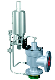
Pilot Operated Safety Relief Vale
|
6250 psig
|
505°F (1.200°F with heat Exchange)
|
ASME Section VIII
|
2900 PV Pop Action, Non Flowing Pilot Operated Safety Relief ValvesThe CONSOLIDATED 2900 PV pop action non-flowing pilot provides excellent performance with full lift at set pressure with minimal blowdown. Specifications: Intel Sizes
1″ to 12″ flanged
Intel Ratings (for flanged valves)
ANSI Class 150 to 2500
Outlet Sizes
2″ to 16″ flanged
Outlet Ratings (for flanged valves)
ANSI Class 150 and 300
Orifice Sizes
Sixteen sizes – D through W
Set Pressure Range
15 psig to 6250 psig
Temp. Range
-4.0F to 5.05F
Materials
Stainless steel pilot with carbon steel main base with stainless steel trim. Complete stainless steel main valve and other exotic materials are available.
Code
ASME Section VIII
 |
|||
|
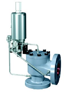
Pilot Operated Safety Relief Valve
|
6250 psig
|
505°F (650°F With Heat Exchanger)
|
ASME Section VIII
|
3900 PV Pop Action, Non-Flowing Pilot Operated Safety Relief ValveThe CONSOLIDATED 3900 PV pop action non- flowing pilot provides excellent performance with Specifications: Intel Sizes
1″ to 10″ flanged
Intel Ratings (for flanged valves)
ANSI Class 150 to 2500
Outlet Sizes
2″ to 10″ flanged
Outlet Ratings (for flanged valves)
ANSI Class 150 and 300
Orifice Sizes
Fourteen Sizes – D through T plus 1-1/2″ to 10″ full bore
Set Pressure Range
15 psig to 6250 psig
Temp. Range
-40°F to 505°F
Materials
Stainless steel pilot with carbon steel main base with stainless
steel trim. Complete stainless steel main valve and other exotic materials are available. Code
ASME Section VIII
 |
|||
|
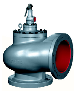
POSRV for High Capacity Steam
|
300 psig
|
550°F
|
ASME Section VIII
|
13900 Pop Action, Flowing Pilot Operated Safety Relief ValveThe CONSOLIDATED 13900 pilot operated safety relief valve series is designed to Specifications: Intel Sizes
16″ to 20″ flanged
Intel Ratings (for flanged valves)
ANSI Class 300
Outlet Sizes
18″ to 24″ flanged
Outlet Ratings (for flanged valves)
ANSI Class 150
Orifice Sizes
114 sq. in. to 201 sq. in.
Set Pressure Range
50 psig to 300 psig
Temp. Range
-250°F to 550°F
Materials
Carbon steel body with stainless steel trim.
Code
ASME Section VIII
 |
|||
|
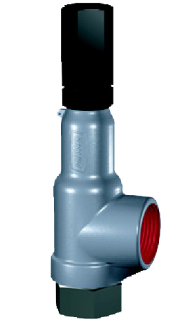
Multipurpose Safety Relief Valve
|
8000 psig
|
1100°F
|
ASME Section III & VIII
|
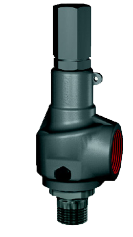
19000 Series PRVThe 19000 Series of pressure relief valves are ASME B & PVC, Section VIII compliant for liquid service applications. Seat tightness, blowdown and capacity on all types of media meets the industry needs for overpressure protection in Specifications: Intel Sizes
1″ to 12″ flanged, Grayloc® or sanitary fitting design
Intel Ratings (for flanged valves)
ANSI Class 150 to 2500
Outlet Sizes
1″ to 2-1/2″ threaded, socket weld, butt weld, flanged or sanitary
fitting design. Outlet Ratings (for flanged valves)
ANSI Class 150 and 300
Orifice Sizes
096 sq. in. to .567 sq. in
Set Pressure Range
15 psig to 8000 psig
Temp. Range
-425°F to 1100°F
Materials
Stainless steel, Monel, Hastelloy, Alloy 20, and other exotic
materials are available Code
ASME Section III and VIII
 Introduction The 19000 Series valves are designed and manufactured in compliance with ASME B & PVC, Section VIII and Section III (Class I, II and III) as well as being CEN compliant to the European proposed standards for safety valves. Seat tightness, blowdown and capacity on all types of media meets the industry needs for overpressure protection in chemical, petrochemical, refinery, power generation (nuclear and conventional) and other commercial applications. General Information The 19000 Series threaded safety relief valve has 316 stainless steel trim as standard material. Reliable performance and easy maintenance procedures are characteristics of this valve (when properly installed in suitable applications for its design). Design Options a. 0-Ring seat seal valves All 19000 Series valves are available with an 0-Ring seat seal, as a design option. This optional design provides a bubble tightness in excess of 97% of the valve set pressure, in order to meet application requirements beyond the normal capabilities of metal to metal seat valves. 19000 Series valves with the 0-Ring seat seal option are identified by the suffix DA (e.g., 1-19096L-DA). b. Lifting Levers, Caps and Gags All 19000 Series valves are designed so that field conversion from the standard screwed cap to a plain lifting lever cap, or to a packed lifting lever cap (or vice versa) does not require valve assembly during resetting. The lifting lever option is designed to open the valve at 75% of the valve set pressure, in compliance with ASME B & PVC, Section VIII. Further, all available 19000 Series valve caps may be equipped with a gag, upon customer request. c. Inlet/Outlet Connections All 19000 Series valves can be provided by CONSOLIDATED with flanges, threaded or socket weld inlet/outlet connections upon customer request. 19000 Standard Valves This product is normally supplied with threaded inlet and outlet connections. Socket weld or flanged end connections are available as well. Springs of precipitation hardened stainless steel are specified for -75°F to 800°F (-59°C to 426.6°C) and the valves carry a “c” suffix in that case. Inconel springs are used for temperatures 801 °F to 1100°F (427.2°C to 593.3°C) and the valve carries a “t” suffix. When selecting valves for back pressure applications, the following limits apply.
Product variations consist of:
Product material variations include:
 |
|||
|
Conventional Safety Relief Valve
|
6200 psig
|
1500°F
|
ASME Section III & VIII
|
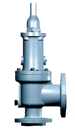
1900 SeriesThe 1900 Series of pressure relief valves provides a wide scope of design in both pressure and temperature ranges. ASME B & PVC, Section VIII certified for vapor, liquid and steam applications meets most overpressure protection requirements of today’s industry. Check the tabs below for additional product information and option. Specifications: Intel Sizes
1″ to 12″ flanged, Grayloc® or sanitary fitting design
Intel Ratings (for flanged valves)
ANSI Class 150 to 2500
Outlet Sizes
2″ to 16″ flanged
Outlet Ratings (for flanged valves)
ANSI Class 150 and 300
Orifice Sizes
Sixteen sizes – D through W
Set Pressure Range
15 psig to 6250 psig
Temp. Range
-450°F to 1500°F
Materials
Cast carbon steel body with stainless steel trim is standard.
Special alloys are available for specific applications. Code
ASME Section III and VIII
Introduction The comprehensive line of spring loaded CONSOLIDATED safety relief valves represents over one hundred years of valve manufacturing experience in meeting and solving industry problems involving a wide scope of valve applications. The flanged CONSOLIDATED safety relief valve line consists of valves in a variety of sizes and materials. Each product offering is unique and judgements are required in selecting the proper option. To accomplish the selection process start with the General Information section of this catalog and follow the prescribed steps necessary to finalize the selection. This Section, 1900 SRV, should be reviewed against the user’s specifications and product offerings selected. Beyond this step, proceed with sizing and then confirmation of the pressure and temperature limits (API or ASME). 1900 Flanged Series safety relief valves are supplied in many variations to suit specific applications. Product variations covered in subsequent pages are noted below:
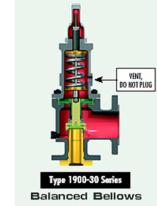
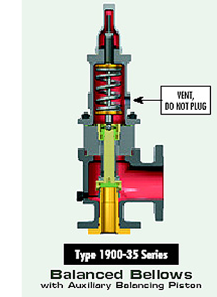
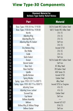
 1900 Series Conventional Safety Relief Valves Steel, Flat Seat, Top Guided, High Capacity, Stainless Steel Trim This standard rugged configuration is equipped with corrosion resistant trim and a carbon steel body, bonnet and cap. The components are top guided, providing for free and repeatable action. The flat disc seat provides for easy maintenance and remachining. The exclusive “Eductor Tube” minimizes bonnet cavity pressure so that product performance is predictable. The nozzle is bottom inserted and rigidly held in position, providing a corrosion resistant path of flow to the valve and corrosion resistant seating surfaces. 1900-30 Series Bellows Construction This valve is the same as the conventional design except that a bellows has been added. When the bellows is installed, the eductor tube is removed. Caution: It is important that the bonnet be vented to the atmosphere. A bellows is added to the conventional valve to deal with any of several situations: Back pressure entering the valve through the valve outlet is excessive or variable. If back pressure fluctuates with ±10% of a nominal value, a bellows is required. If a built up back pressure exceeds 10% of the set pressure or cold differential set pressure, a bellows must be used. If the entering fluid is a slurry, highly viscous, or of a nature that it can enter the critical clearances between the guides/disc holder, protect that area with a bellows. If the fluid being handled is corrosive to the upper works of the valve, isolate the bonnet chamber through use of a bellows. Conventional valves can be easily converted to a bellows design or vice versa through the use of retrofit kits. All CONSOLIDATED 1900-30 Series valves are balanced bellows designs, meaning that they fully compensate for the effects of back pressure. 1900-35 Series Balanced Bellows (with Auxiliary Balancing Piston) The Balanced Bellows seals the body and fluid stream from the bonnet and working parts. Auxiliary balancing piston assures proper valve performance by compensating for back pressure in case of bellows failure. The use of an auxiliary balanced piston is indicated when: back pressure (either constant or variable) exists and; excessive pressure may build in the bonnet as a result of pressure build-up in the bonnet vent piping and; resultant build-up of pressure in the bonnet would cause a dangerous condition. Codes and Standards The Consolidated 1900 series is compliant with the following codes and standards: ASME B & PVC, Section II – Material (Applicable as required by ASME B & PVC, Section III or VIII) ASME B & PVC, Section III, class 2 and 3 (Gas, Vapor, and Liquid Service) ASME B & PVC, Section VIII (Gas, Vapor, and Liquid Service) ASME B16.34 and ASME B16.5 API 520, 526 and 527 ISO 4126 NACE MR0175 Standard Material Requirements API Standard 526-1995 Safety relief valves specified within this catalog comply with API standard 526 – Fourth Edition, 1995. The 1900 Series valves previously complied with API standard 526 – Third Edition, 1984. In some cases dimensional and nominal flanges sizes differ between these two editions. When ordering replacement valves that must comply with API Standard 526 – Third Edition, 1984, contact the factory for verification of the correct replacement.
|
|||
|
Safety Relief Valve
|
5000 psig
|
850°F
|
ASME Section I
|
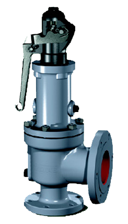
1900 P1 and P3Standard in both types, the patented Thermodisc” Seat is designed for a Specifications: Intel Sizes
1″ to 8″ flanged
Intel Ratings (for flanged valves)
ANSI Class 150 to 2500
Outlet Sizes
2″ to 10″ flanged
Outlet Ratings (for flanged valves)
ANSI Class 150 and 300
Orifice Sizes
Fourteen sizes – D through T
Set Pressure Range
15 psig to 5000 psig
Temp. Range
-20°F to 850°F
Materials
Carbon Steel body with stainless steel is standard.
Code
ASME Section
 |
|||
|
High Capacity, Low Pressure
Applications |
500 psig
|
800°F
|
ASME Section I
|
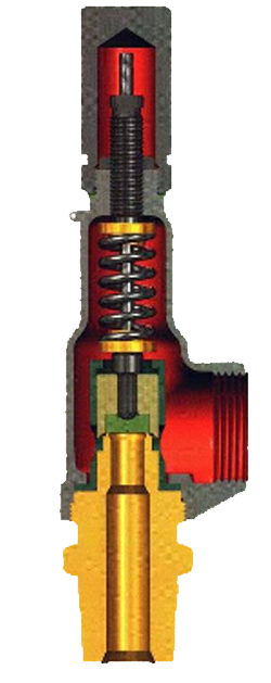
1982 Pressure Relief ValveASME B & PVC, Section VIII certified threaded connection pressure relief Specifications: Intel Sizes
1/2″ to 2″ threaded
Intel Ratings (for flanged valves)
Outlet Sizes
3/4″ to 2-1/2″ threaded
Outlet Ratings (for flanged valves)
Orifice Sizes
Five sizes – .121 sq. in. to 1.399 sq. in.
Set Pressure Range
15 psig to 5000 psig
Temp. Range
-20°F to 800°F
Materials
Stainless steel base with stainless steel trim is standard.
Code
ASME Section VIII
 |
|||